CAN Topology: A Simple Guide for Beginners
Published: February 23, 2025
If multiple devices need to communicate in a system, do they always require a central computer? Not necessarily! CAN topology eliminates the need for a host computer, allowing microcontrollers to exchange data efficiently over a shared bus. But how does it achieve seamless communication while preventing data collisions? Let’s find out.

What is CAN Topology?
CAN topology stands for Controller Area Network topology. It is a network structure used to communicate between multiple microcontrollers and electronic devices without a central host computer. It is widely used in automotive, industrial automation, and medical systems for real-time data exchange.
Why is CAN (Controller Area Network) Topology Important?
1. Reliability
Built-in error detection ensures accurate data transmission, even in noisy environments.
2. Efficiency
Short message frames reduce delays, making it ideal for real-time applications.
3. Scalability
CAN networks can support multiple devices without performance issues.
Key Components of CAN(Controller Area Network) Topology
CAN topology consist of several essential components that work together to enable efficient and reliable communication between devices? Here’s a breakdown of its main components:
1. Nodes (ECUs – Electronic Control Units)
Nodes, called Electronic Control Units (ECUs), are devices connected to the CAN network. Each node can send, receive, and process messages based on priority. In an automotive system, for example, different ECUs control functions like the engine, braking system, airbags, and infotainment. These nodes communicate over the CAN bus without needing a central computer.
2. CAN Bus
The CAN bus is the physical communication channel that connects all nodes in the network. It consists of two twisted wires (CAN High and CAN Low) that help reduce electromagnetic interference. This bus structure allows multiple devices to share data without interfering with one another, ensuring smooth and synchronized communication.
3. Terminators
Termination resistors (typically 120Ω) are placed at both ends of the CAN bus to prevent signal reflections and data corruption. These resistors absorb excess signals, ensuring data integrity and stable communication. Without proper termination, the network could experience errors or transmission failures.
4. Transceivers
A CAN transceiver converts digital signals from the controller into electrical signals that can be transmitted over the CAN bus. It also translates incoming electrical signals back into digital form for processing, ensuring that messages are accurately transmitted and received by each node.
5. Controllers
The CAN controller manages the network’s communication process. It prioritizes messages, ensuring that high-priority data (e.g., braking system commands) are sent before less critical messages (e.g., infotainment updates). Additionally, the controller handles error detection and correction, improving the network’s reliability.
Types of CAN Topologies
Different CAN (Controller Area Network) topologies are used depending on the application’s requirements. Each type has advantages and limitations.
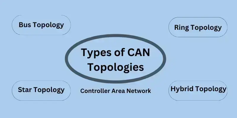
1. Bus Topology (Standard CAN Network)
It is the most common topology used in automotive and industrial systems.
✅ Advantages
Simple and easy to implement.
Cost-effective due to minimal wiring.
Efficient for real-time communication.
❌ Disadvantages
Performance issues in large networks.
A single point of failure (e.g., a broken bus) can disrupt communication.
📌 Where It’s Used
Automotive control systems, industrial automation.
2. Star Topology
Each node connects to a central hub, making it more fault-tolerant.
✅Advantages
If one connection fails, other nodes continue communication.
Better performance in some cases due to reduced signal interference.
❌ Disadvantages
Requires more wiring, increasing cost and complexity.
If the central hub fails, the entire network is affected.
📌 Where It’s Used
Industrial networks, complex automotive designs.
3. Ring Topology
Nodes are connected in a circular structure, ensuring data redundancy.
✅ Advantages
If one connection breaks, data can still travel in the opposite direction.
Reliable for critical applications requiring high fault tolerance.
❌ Disadvantages
More complex to implement than bus topology.
Slower response time due to data travelling through multiple nodes.
📌 Where It’s Used
Advanced industrial automation, high-reliability systems.
4. Hybrid Topology
A combination of two or more topologies (e.g., Bus + star) used in complex systems.
✅ Why It’s Used
- Provides flexibility and better fault tolerance.
- Balances cost, performance, and reliability based on system needs.
How CAN Topology Works?
CAN topology allows multiple devices to communicate efficiently without a central host. It uses a unique protocol to manage data transmission and avoid message collisions.
1. Message Transmission Using CSMA/CD
CAN networks use Carrier Sense Multiple Access with Collision Detection (CSMA/CD) to transmit messages.
- Carrier Sense (CS): Each node listens to the Bus before sending data. If the Bus is free, the node starts transmission.
- Multiple Access (MA): Multiple nodes can access the Bus, but only one message is transmitted at a time.
- Collision Detection (CD): If two nodes send messages simultaneously, the priority-based arbitration system determines which message gets through first.
- It ensures efficient communication and prevents data loss.
2. Priority-Based Arbitration in CAN Messages
Each CAN message has an 11-bit or 29-bit identifier that determines its priority.
- The lower the identifier number, the higher the priority (e.g.,””Engine Failure Warning”” will be prioritized over””Radio Volume Chang””).
- If two nodes send data simultaneously, the one with the lower identifier continues, while the other stops and retries later.
It prevents delays in critical vehicle functions and ensures smooth operation.
3. Real-World Example: How a Car’s Sensors Communicate Using CAN Topology
Imagine a car equipped with CAN topology:
- The brake sensor detects sudden braking.
- It sends a high-priority message to the CAN bus.
- The engine control unit (ECU) receives this message and reduces power.
- The airbag system also gets the data and prepares for possible deployment.
- Meanwhile, a low-priority request (like adjusting the radio) is temporarily delayed.
- This system ensures fast, real-time responses, improving vehicle safety and efficiency.
Real-World Applications of CAN(Controller Area Network) Topology
CAN topology is widely used in industries where real-time, reliable, and efficient communication is critical. Here are some key areas where it plays an essential role:
1. Automotive Industry 🚗
CAN networks are the backbone of modern vehicle communication. They allow different components, such as the engine, brakes, airbags, sensors, and infotainment systems, to exchange data without a central computer. It ensures:
- Faster response times for safety systems.
- Efficient power management in hybrid and electric vehicles.
- Seamless control of vehicle functions like ABS and traction control.
2. Industrial Automation 🏭
Factories and production plants use CAN(Controller Area Network) topology to connect machines, robotic arms, and sensors. It helps in:
- Coordinating automated assembly lines for high efficiency.
- Monitoring sensor data to prevent machine failures.
- Reducing wiring costs compared to traditional networks.
3. Medical Equipment 🏥
CAN networks enable real-time data exchange between medical devices like:
- Patient monitoring systems, ensuring quick response to health changes.
- MRI and CT scanners for high-precision imaging.
- Infusion pumps, to regulate drug delivery with accuracy.
4. Aerospace and Defense ✈️
Reliability is crucial in aircraft and military vehicles. CAN topology ensures:
- Stable communication between flight control systems.
- Real-time data transfer for navigation and diagnostics.
- Improved safety and automation in uncrewed vehicles.
Future of CAN(Controller Area Network) Topology
As technology advances, CAN(Controller Area Network) topology is evolving to meet modern demands.
1. CAN FD (Flexible Data Rate) for Speed Improvements
Traditional CAN networks have speed limitations (1 Mbps max). CAN FD (Flexible Data-Rate) allows:
- Faster data transmission (up to 8 Mbps).
- Larger message sizes, improving efficiency in complex systems.
- Better real-time performance for advanced automotive and industrial applications.
2. Integration with IoT and AI
- CAN networks are integrated with IoT (Internet of Things) for intelligent automation.
- AI-powered CAN systems can predict failures and optimize performance.
3. Wireless CAN Networks
- Future wireless CAN solutions may eliminate the need for physical wiring.
- It would reduce costs, improve flexibility, and enable remote monitoring in smart cities and autonomous vehicles.
CAN topology is evolving to become faster, wiser, and more adaptable to modern needs.
Conclusion
CAN topology is a trusted communication framework in industries where real-time, reliable, and efficient data transfer is crucial. CAN networks enhance safety, efficiency, and automation from automobiles and factories to hospitals and defence.
With advancements in CAN FD, IoT, and AI, the future of CAN topology looks even more promising. If you work on automotive, industrial, or medical projects, adopting CAN-based systems can help you build smarter, more efficient networks.
Interested in implementing CAN topology? Start exploring its applications and see how it can revolutionize your industry!
FAQs About CAN(Controller Area Network) topology
No, CAN topology refers to the physical structure of how devices are connected, like bus or star topology. The CAN protocol is the communication rule devices follow to send and receive messages.
Yes! Unlike traditional networks, CAN allows devices (nodes) to communicate directly without a central controller. It makes it faster, more reliable, and cost-effective for real-time applications.
CAN networks use two twisted wires (CAN_H and CAN_L) to reduce signal interference and ensure accurate data transmission. This setup improves communication stability, even in noisy environments like cars and factories.
CAN uses priority-based arbitration, meaning the higher priority (lower identifier) message gets sent first. The other device waits and retries, ensuring no data collisions or loss.
Not necessarily! Thanks to error detection and fault confinement mechanisms, the rest of the network can still function if a device fails. However, repeated failures may affect performance.
Termination resistors (typically 120Ω at both ends) prevent signal reflections, which can cause communication errors. Without them, the network may experience data corruption and instability.
Unlike RS-232 or UART, CAN supports multiple devices on the same Bus, prioritizes messages, and has built-in error handling. This makes it more efficient for real-time applications like automotive and industrial systems.
Traditional CAN networks use wired connections, but Wireless CAN (WiCAN) is emerging for IoT and intelligent automation. Compared to wired CAN, WiCAN faces challenges like latency and interference.
CAN FD (Flexible Data Rate) is an upgraded version of CAN that allows faster speeds (up to 8 Mbps) and larger data frames. It is ideal for modern cars, industrial automation, and AI-powered systems.
CAN enables real-time communication between engines, brakes, airbags, and sensors, ensuring instant response to critical situations. For example, if the brakes are applied suddenly, the CAN system alerts the engine and airbags within milliseconds.
| “Support justice ✊ — 🚫 Boycott Israeli Products” |
|---|